Calibration Example
In This Topic
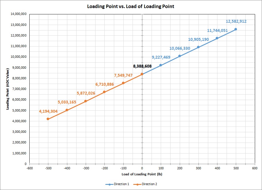
The following example provides a graphical representation of a 5-point calibration that was performed in two directions using a USB210. Each direction contains data related to the physical load (Load of Loading Point (lb)) and the input voltage (Loading Point (ADC Value)). Depending on the type of board used, there can be several loading points applied during calibration.
| Direction 1 | ||
|---|---|---|
| Point | Load of Loading Point (lb) | Loading Point (ADC Value) |
| Loading Point 0 | 000.00 | 8388608 |
| Loading Point 1 | 100.00 | 9227469 |
| Loading Point 2 | 200.00 | 10066330 |
| Loading Point 3 | 300.00 | 10905190 |
| Loading Point 4 | 400.00 | 11744051 |
| Loading Point 5 | 500.00 | 12582912 |
| Direction 2 | ||
|---|---|---|
| Point | Load of Loading Point (lb) | Loading Point (ADC Value) |
| Loading Point 7 | 000.00 | 8388608 |
| Loading Point 8 | -100.00 | 7549747 |
| Loading Point 9 | -200.00 | 6710886 |
| Loading Point 10 | -300.00 | 5872026 |
| Loading Point 11 | -400.00 | 5033165 |
| Loading Point 14 | -500.00 | 4194304 |